(The time switch can be automatically adjusted according to the latitude and longitude of the switching time.)
1. Function and Scope
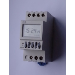
NKG-3 time switch (hereinafter referred to as time switch) is applicable for regularly controlling switch-on and off of street lamps, advertising light boxes and other equipments in automatic control circuit with AC frequency of 50Hz, rated control power voltage of 220V at most and rated working current of 3A at most. The product may be used to adjust the switch-on and off time everyday according to the latitude.
The product complies with the requirements of Standard GB 14048.5 and IEC 60947-5-1.
2. Model and Its Meaning
Operating Voltage
Number of control circuit
Without: control circuit one
Design No.
Time switch
Enterprise code
3. Normal Operating Condition and Installation Condition
3.1 Ambient air humidity: -5~+40, and the average temperature is no more than +35 in 24h.
3.2 Altitude: no more than 2,000m.
3.3 Humidity: the relative air humidity of the installation site shall be no more than 50% when the maximum temperature is +40, while it can be higher under lower temperature. Special measures shall be taken for the condensation occasionally formed due to temperature change.
3.4 Pollution level: 3.
3.5 In the medium with explosion hazard and no gas that is enough to corrode metal and destroy the insulation and the place shall not have severe conductive dust.
3.6 In the place where is provided with anti-snow and anti-rain equipment but not be full of water steam.
3.7 In the place without significant shake, shock and vibration.
3.8 Installation class: II.
3.9 Transport and Storage Conditions: -25 to +55.
3.10 Power voltage change scope: 85%~110% rated operating voltage.
3.11 Protection grade: IP20.
4 Main Technical Parameters
4.1 Rated control power voltage: 50Hz AC220V.
4.2 Conventional thermal current: Ith 16A.
4.3 Category of the control circuit: AC-15.
4.4 Rated working current (Ie): AC-15 220V 3A.
4.5 Timing error: ?1s/d.
4.6 Time control scope: 1min~168h.
4.7 Dimension setting range: N/S -60 ° ~+60 °.
4.8 Mechanical life: ?30,000 times.
4.9 Electric endurance: ?10,000 times.
4.10 Installation method: Device installed, guide tracked.
4.11 Anti-interference tolerance sees Table 1.
Table 1 Anti-interference Tolerance
Item
Severity
Static discharge tolerance
8 × (1±10%) KV (air discharge)
Electromagnetic radiation tolerance
Test field strength 10 × (1±10%) V/m
Fast transient tolerance
For power line: 2 × (1±10%)KV, duration 1min
Surge (shock) tolerance
For power line:1 × (1±10%)KV
RF conduction tolerance
Open circuit test voltage 10V, frequency scope 150kHz~80MHz
Voltage sage tolerance
Sag 30% in half a cycle, sag 60% in 5 cycles and 50 cycles, sag 100% in 250 cycles
5 Outline, Installation Dimension and Wiring Method
5.1 Outside dimension and installation dimension see Figure 1.
a) NKG-3 outside dimension b) NKG-3 installation imension
Figure 1 Outside dimensions and installation dimensions of NKG-3
5.2 Wiring method
5.2.1 Direct control method
Power of the controlled appliance is supplied in single-phase, of which the working current is no more than the rated value of this switch. Direct control method may be adopted, wiring method see Figure 2; for light load with great starting current impact, please adopt AC contactor expansion control method.
5.2.2 Single-phase expansion method
The controlled appliance is power supplied in single-phase, of which the working current exceeds the rated value of this switch. Please adopt AC contactor expansion control method, see Figure 3.
5.2.3 Three-phase operating method
Power of the controlled appliance is supplied in three-phase, so external AC contactor is required hereof.
A) The coil voltage of the controlled contactor is AC 220C 50Hz, so its wiring method sees
Figure 4;
b) The coil voltage of the controlled contactor is AC 380V 50Hz, so its wiring method sees
Figure 5.
Figure 2 Direct single-phase controlled wiring diagram Figure 3 Single-phase expansion controlled wiring diagram
Figure 4 Three-phase controlled wiring diagram (220V for contactor coil) Figure 5 Three-phase controlled wiring diagram (3800V for contactor coil)
6 Setting and Use
This product panel is set with five buttons, namely MD (mode), R (recall), (shift), (-) and (+), so it can adjust correspondingly hour (h), minute (min) and date; if there is some operating indication, time switch may be controlled manually or automatically.
6 Setting and Use
This product panel is set with five buttons, namely MD (mode), R (recall), (shift)”, (-) and (+), so it can adjust correspondingly date (d), latitude ( ), hour (h) and minute (min), and it can also set second (sec) in clock status.
6.1 Setting process for timing switch parameters (see Figure 6).
6.2 Setting processes are as follows:
6.2.1 Firstly power-on or press button MD + R to enter latitude setting interface
6.2.1.1 Current latitude and date adjustment
6.2.1.2 Press to adjust latitude, for example, local latitude 30°N shall be adjusted to N: 30; while local latitude 15°S shall be adjusted to S: 15, see Figure 7.
Figure 7
6.2.1.3 Press MD to enter current date adjust status, press to select the adjusted position, press " ” and " ” to plus and minus, adjust the display date of the product to current date, such as current March 15 shall be set to 03: 15d, see Figure 8. After setting, press MD to exit.
Figure 8
6.2.2 Current time adjustment
6.2.2.1 Press button MD for 3s to cancel the keyboard lockout, so that LOCK may disappear, the current min position flashes, you can press " ” to select the adjusted position and press " ” and " " to plus and minus, so as to adjust the display time to the current time, see
Figure 9.
6.2.3 Timing parameters (switch-on/off time) setting
6.2.3.1 After finish operation in 6.2.2, press MD to set the timing parameters, and the corresponding position flashes, see Figure 10.
Figure 10
6.2.3.2 1ON (first switch-on) time setting: press "”, "" and "" respectively to set 1ON time, the latitude marks the latitude adjustment function; after setting hour, press to enter latitude mark setting model, by then, screen does not flash, and press and to switch on/off the latitude adjustment function; after finishing this, press MD to enter 1OFF (first switch-off) time setting, see Figure 11.
Figure 11
6.2.3.3 1OFF (first switch-off) time setting: set 1OFF time according to steps specified in 6.2.3.2.
6.2.3.4 Continue to press MD , For redundant time period, please press"R” to remove the time of other groups, so that the liquid-crystal display will show "”, see Figure 12, and then, press"R” to recall.
Figure 12
6.2.4 After setting, press "MD” for 3s, enter operation state, the time switch locks automatically, "LOCK” shows, and see Figure 13.
Figure 13
6.3 After locking the switch, press "MD” and " ” at the same time to switch manual/automatic status. Continuously press the combination, the screen will show "OFF”, "AUTO OFF”, "ON” and "ON AUTO” successively, see Figure 14. When the circuit shall be on and off temporarily in the process of operation, the combination buttons can be used to adjust the switch to ON and OFF; if the time switch shall work automatically according to the set time, the combination button shall be used to adjust the switch to "ON AUTO” or "AUTO OFF, then the time switch may work as set time, so as to achieve automatic control, see Figure 14.
Figure 14 Manual/automatic time switch setting process
7 Notes
7.1 please push the blue limiting piece In the bottom of product before use.
7.2 The switch into the line can only be connected to AC220V power supply, do not access the other power.
7.3 If you can not achieve automatic control function,Check the lower right corner of the screen (AUTO) is right shown?
7.4 The internal battery can only provide the LCD screen display and settings, such as A1, A2 terminal auxiliary power missed, is unable to drive the relay output..
7.5 If the user find errors in the products,Through short 3, 4 terminal reset,After reset procedures need to set again.
7.6 If the latitude function of some group of setting time is open, the set time may be automatically adjusted by changing the current latitude and date, so please check once more the set time after changing the latitude and date.
7.7 When the end of the product life, please recycle work product or its components, for not recycled parts, please dispose of, to protect our environment.